|
Axial Operation |
Thread rolling remains a simple and efficient process, provided the three main conditions listed below are met and adhered to at all times: |
|
The material to be rolled must be suitable for
thread rolling (refer to material properties - Click Here). Attempting to roll unsuitable material may at best give poor thread quality, and at worst cause severe damage to both the rolls and the thread rolling head.
The correct rolling speed should be selected according to the material being rolled and the profile of the thread form required. Reference to material properties (click Here), and the rolling speeds chart (Click Here) will enable the correct spindle speed to be calculated. For most standard V-form threads such as unified, metric & Whitworth, 100 ft/min (30m/min) should be considered as the absolute minimum speed, with only Acme, trapezoidal and similar thread forms being attempted at speeds as low as 65 ft/min (20m/min). Attempting to roll at too low a speed will most likely result in premature thread roll failure. Conversely, a higher rolling speed will often improve a material’s rolling characteristics, thus improving thread roll life. |
|
An adequate supply of good quality coolant is essential for successful thread rolling, as it is for most machining processes. The choice between neat cutting oils and water soluble is often governed by the type of machine being used or, where applicable, the user's environmental / health and safety policy. While neat cutting oils normally possess superior lubricating and extreme pressure properties, they do not dissipate heat away from the rolls as efficiently as water soluble solutions, unless some type of refrigeration unit is incorporated into the coolant system. When mixing soluble oils it is advisable to maximize the ratio of oil to water, as this gives the best combination of lubrication and cooling properties needed for thread rolling. Finally, once the choice of coolant has been made, ensure the supply is both copious and free of metallic particles. An insufficient supply will soon result in the rolls overheating, while particulate contamination can cause damage to the thread rolls, their bearings and the head mechanism. |
|
Having satisfied the principal machining conditions outlined above, the following steps should be followed when setting up for each thread size: |
|
|
Such is the variety of components that can be rolled it is impossible to illustrate the pre-rolling blank for every application. However, with few exceptions, component blanks fall in to one of three following categories: |
|
A. Rod/tube drawn or ground to pre-rolling size. |
When producing studs, linkages, U-bolts, conduit and similar parts, pre-machining can be eliminated by
careful selection of material stock that has been drawn or ground to the correct pre-rolling diameter. The increasing popularity of thread rolling has resulted in rod and tube mills offering many standard materials in a range of pre-rolling diameters for most commercial thread sizes. It is often found the blank diameter will be at or within .002"/.05mm of the threads effective diameter, but before committing production to any given supply of bar stock, it is advisable to run sample batches in order to determine that both the basic stock size and tolerance will suit the application. Consideration should be given to the fact that a variation in blank diameter will affect the resultant major diameter by a ratio of approximately three to one when rolling directly on to bar stock. For example, if a drawn rod is supplied with a tolerance of nominal size 0.0/-0.002" (0.0/-0.05mm), then the rolled major diameter will have a tolerance band of 0.006" (0.15mm) which is allowable for most threads of class 2A and 6G fit. If a tighter tolerance on major diameter is required, then ground stock should be considered ahead of drawn stock. |
|
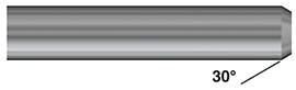
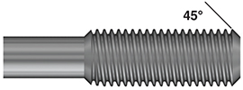
Once the correct diameter of bar or tube has been selected, it only remains for the blank to be pre-
chamfered to facilitate the initial engagement of the rolls and leave the finished piece part with a clean lead in thread (See figures 3 & 4). |
|
Figure: 3 Pre-rolled rod |
|
Figure: 4 Rod after rolling |
|
| |
B. Blank pre-turned up to a shoulder. |
| Most thread rolling applications involve the piece part being turned in the spindle prior to the actual rolling process. This has the distinct advantage the blank and the rolling head will be in line which eliminates the problems involved with misalignment. The required blank diameter will need to be determined by machining several trial parts to the following procedure:
1. The rolling head has to be adjusted as close as possible to its final running position. With the head in its closed position, a plain plug, turned to the minor diameter of the thread, is placed between the thread rolls in the head. The three nuts (part number 15) are slackened off and the head is adjusted down so that the rolls grip the plug. The plug is then removed and the head adjusted down 1/2 a division on the graduated scale to remove any play in the bearings.
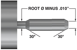
2. The piece part is turned down to the pitch diameter, minus .002"/.05mm, with a chamfer machined to .010"-.020" (.25mm-.5mm) below the root diameter. The angle of the chamfer should be no more than 30 degrees to the axis, with 20-25 degrees being ideal (See figure 5). After rolling, the resultant chamfer should be approximately 45 degrees, due to the flow of material at this point (figure 6). |
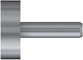 |
Figure: 5 Before rolling |
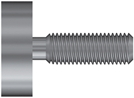 |
Figure: 6 After rolling |
|
3. The opening position of the rolling head is then determined by advancing it forward, in the open
condition, until the front faces of the rolls are just short of the shoulder. On a conventional machine, the mechanical stops would be set at this point, whereas on a CNC machine the Z-axis position should be noted and used as the end point in the program. This procedure should be undertaken with the spindle stationary and as previously stated, with the head in the open condition.
4. With the head set to the approximate size, and the blank turned to the lowest estimate of the required pre-rolling diameter, the first attempt at rolling is then made, using the appropriate spindle speed for the thread being rolled and advancing the head at, or just below, the required feed rate (1 X pitch/rev). At the opening position the head stops advancing, allowing it to pull off and trip open as the drive coupling disengages between the shank and spring housing. (A short, half a second dwell on the machine cam or in the CNC program is required to allow the head to open before it is retracted).
It is most likely that the first component rolled following the above procedure will be oversize on the pitch diameter and undersize on the major diameter. If this is the case, then the next step is to adjust the head down another 1/2 division on the graduated scale and then roll another test piece. By adjusting the head down, the pitch diameter will decrease, while the major diameter will increase. After just one or two further test pieces, the pitch diameter should be established to suit the gauges, but the major diameter may still be undersized. If this is the case, calculate the amount by which the major diameter needs to increase and adjust the blank diameter up by a third of this amount. Ideally, when both the pitch and the major diameters are at the middle limit of their tolerances, the crest of the thread should have a slight truncation and not quite be fully formed. A fully formed thread, while giving a smooth and polished appearance, is a sign of over rolling which causes over stressing of the rolls and reduces their working life. |
| |
|
| |
C. Thread rolling into an undercut |
The same principles for thread rolling up to a shoulder apply when thread rolling into an undercut, except for the blank profile at the undercut itself. Here, the chamfer is machined on the front of the blank must also be machined at the undercut, as illustrated in figure 7. |
|
Figure: 7 Blank with undercut |
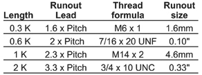
In selecting the width of undercut, consideration should be given for the length of run out required when the thread rolling head opens. Axial thread rolls are available with two standard styles of lead: 1K and 2K.
Rolls designated 1K have one modified lead thread that enables the rolls to engage on the end of the blank and allows for the material to be progressively formed up to the full thread depth. Chosen as the standard short lead, these rolls generate a runout length of 2.3 X P, where P is the pitch of the thread being rolled. This formula allows for the length of the lead on the rolls and for the opening action of the thread rolling head and is therefore only a close approximation. In practice, it may be found that a shorter runout is obtained when a sample component is rolled. |
|
Note: If the standard 1K lead is too long for the desired undercut, rolls can be supplied with special extra short leads of 0.6K or even 0.3K. However, by concentrating the rolling process into a shorter lead, roll life can be significantly reduced. Subsequently, 0.6 and 0.3K leads are only recommended on low tensile, ductile materials.
The preferred standard lead for most thread rolling applications is 2K, as this spreads the working load over two start threads on each roll, giving a general increase in roll life over 1K lead rolls. Due to the extra lead thread on each roll, the runout length on the component will increase by one extra pitch. The following examples show the runout for each type of lead on some typical threads: |
|
|
| |
Assembling Rolls Into Head |
Remove the front plate screws to release the front plate, revealing the eccentric spindles on which the thread rolls are to be mounted. For the A0 head, which has 2 rolls, the rolls are assembled 1-2 or A-B while for all right hand 3 roll heads, the rolls are assembled 1,2,3 or A,B,C in a clockwise direction as viewed by the operator (for left hand thread rolling heads, rolls are assembled counter clockwise).
Before assembly, it is recommended to smear all
contact surfaces with a good quality lubricating grease or paste to minimize friction and wear. This will help protect the rolls, needle bearings and eccentric spindles which perform at high speeds under severe loads.
With the rolls in the correct sequence, insert the needle bearings or carbide bushes, replace the front plate and secure tightly with the front plate screws. Always ensure that the full amount of needle bearings are loaded between the rolls and the eccentric spindles (refer to head breakdown). For example, the A2 head requires 57 needle bearings, which is 19 per roll. Insufficient needle bearings in just one roll will reduce accuracy, promote roll failure and cause excessive wear to the eccentric spindle. This potential problem is eliminated by the use of carbide bushings, which are also quicker and easier to replace and allow roll changeovers to be accomplished with the head still mounted in the machine turret.
With the rolls assembled and the front plate tightened down, it should be possible to rotate the rolls freely by hand. The head can now be adjusted to suit the thread to be rolled by following this simple procedure: |
|
a. Ensure the head is in the closed condition
b. Loosen the 3 nuts (part number 15) which will allow the front cage of the head to be rotated relative to the spring housing. Note the setting line and graduated scale. As the head is adjusted in the minus direction (-), the rolls close down, opening outwards when the head is adjusted in the plus (+) direction.
c. The head can now be adjusted down on to a setting piece, which can be a screwed sample or a plain plug machined to the minor diameter of the thread. If the head is adjusted to either the + or - limit, and is still not to size, remove the 3 nuts and ring washer (part number 16). The front cage assembly is then removed, rotated about 120 degrees in the desired direction of adjustment, and then reassembled on the spring housing. Another indicator will then line up at one end of the graduated scale, permitting further adjustment in the desired direction.
d. When the head has been successfully adjusted
down on to the setting piece, the 3 nuts can then be re-tightened. The first component to be rolled at this setting is invariably oversize, and the head will then need to be adjusted down in 1/2 division increments until the desired pitch diameter is achieved. Any necessary alterations to the blank diameter can now be made to produce the correct major diameter on the thread. |
|
| |
| |
|
|
|